VBit Inlay Plugin for Autodesk® Fusion®
Video References
- VBit Inlays with Autodesk Fusion (2D) – the basic primer on how to do it all.
- VBit Inlays for Cutting Boards – Details on v5 updates for 2D inlays
- 3D Curved VBit Inlays – The extra details on how to do curved inlays
- 3D Carving Process – via Erickson Design & Woodworking
Table of Contents
- Download & Install
- Terminology
- Creating Features / Inlay
- Creating Toolpaths / CAM
- Design: What the Plugin Generates
- Manufacturing: The Plugin Generated Setups
- Parameters
- Finding the Perfect Inlay Fit
- Organization Recommendations
- Using Templates
- V-bit Tool Selection / Tapered Ball Nose (TBN)
- 3D Inlays / Extreme Angles / Machinability
- PROBLEMS? Read this section: Issues / Bugs / Limitations
- Proven Cut Speeds / Feeds / Parameters for Particular Bits
Download & Install
Two ways to install:
- Install from Fusion’s App Store: VBit Inlay by Corbin’s Worksho
- Manual install:
- Download: VBit Inlay Plugin
- Unzip the folder somewhere (ideally your AddIns folder on Fusion)
- In Fusion, click Utilities -> Add-Ins -> Scripts and Add-Ins
- Click the plus icon, and select “Script or Add-In from device”
- Select the folder that you unzipped
- Click the Run button, and optionally set it to Run on Startup
- For more information, see Autodesk’s How to install an add-in or script in Autodesk Fusion
The plugin auto-updates automatically when a new version is released.
Release Notes
- Read the latest release notes here: VBit Inlay Release Notes
License
This software is shareware! If you find it useful and it saved you some time, please purchase a license for $5. The license is a lifetime license for the individual who purchased it. All updates are free.
Terminology
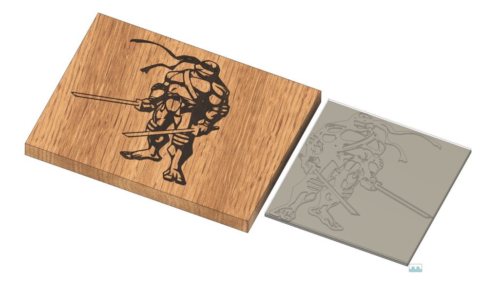
Inlay: The part that fits into the pocket and is at the finished size. In the picture on the right, the inlay is the dark walnut wood. Generally, this is just for looks, and isn’t used for manufacturing.
Female Pocket: The part that the inlay does into, with a pocket v-carved out. The light cherry wood.
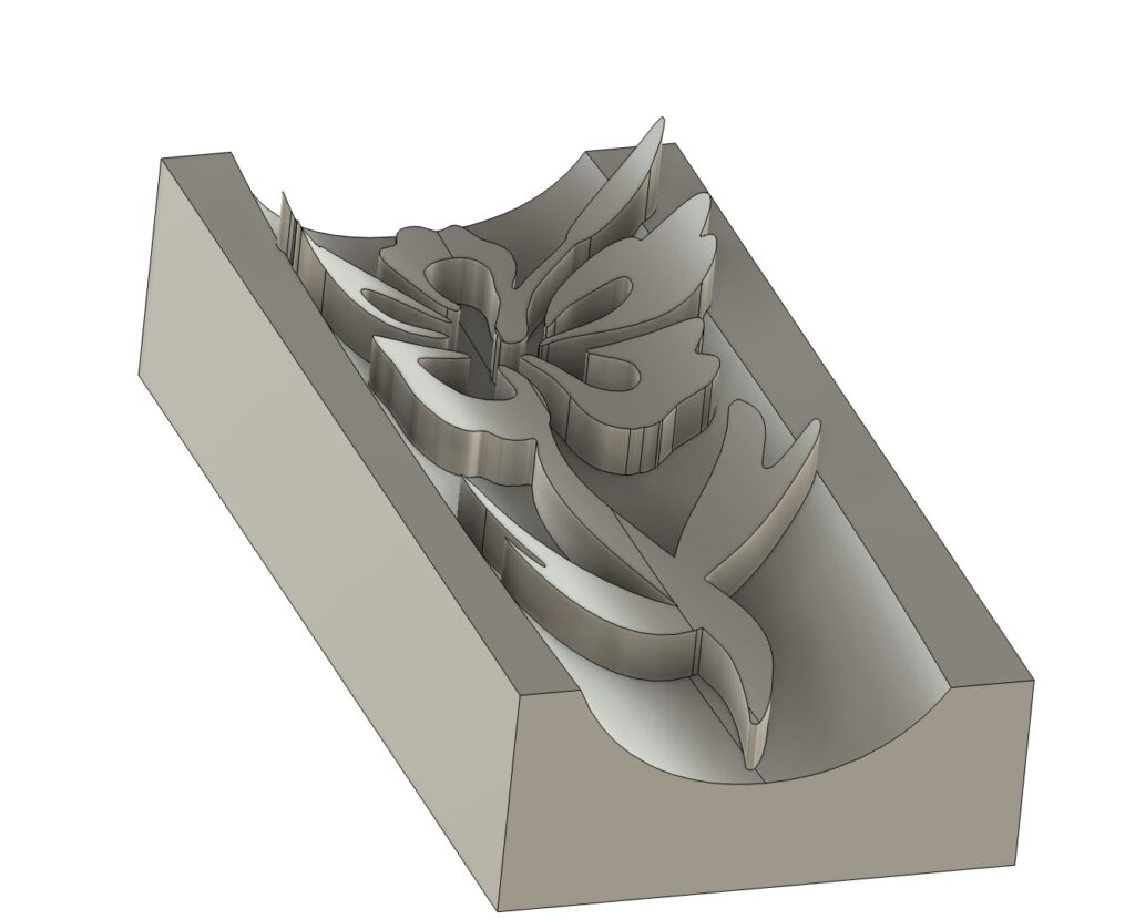
Male Plug: The complete male plug that will fit into the inlay when you are constructing it. This includes a backing, the Base Plug Thickness. It is the gray part in the image.
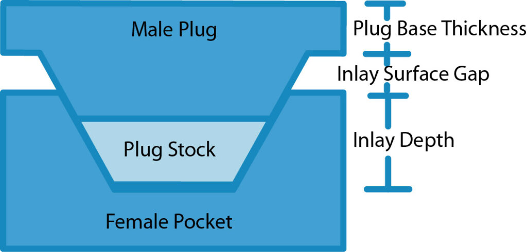
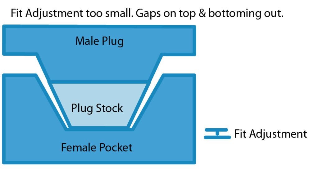
The Inlay Depth is how deep the inlay will go into the Female Pocket. The Male Plug will have a Plug Base Thickness to hold it all together, which you will remove after the inlay glue has dried. The Inlay Surface Gap is the space between the base and the top of the inlay. The Plug Stock is additional material not in the design, but in the stock that allows the inlay to seat correctly (this will be explained more later).
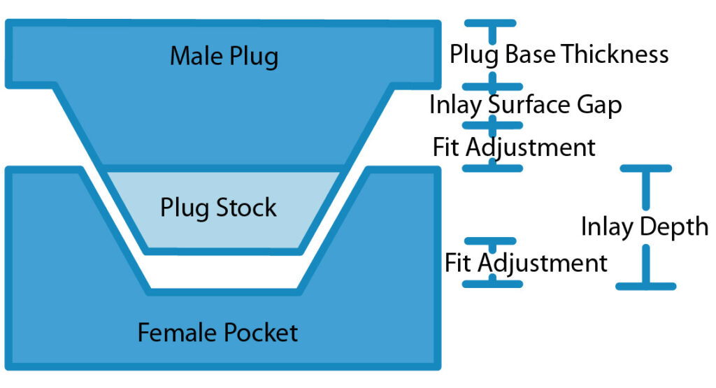
The Fit Adjustment is the only parameter you will modify to get the inlay to fit properly. There is no glue gap! Simply changing the Fit Adjustment will make the fit better, as described later. The Fit Adjustment only affects the plug. You do not have to change the Inlay Surface Gap to get a better fit; pick some value and stick with it, unless you find you need more or less space for some other reason. See “VBit Inlay Parameter List” for some known values that work for me.
A 2D or Flat Inlay is a basic inlay on a flat surface. The toolpaths, and the model will be much simpler and faster to generate, and will attempt to use 2D Toolpaths, such as Engrave and 2D Pocket.
A 3D or Curved Inlay is a complex inlay on a non-planar surface, or across multiple surfaces. The inlay generation is much more complex, and the toolpaths require 3D toolpaths, and take a lot longer to generate.
Creating Features / Inlay
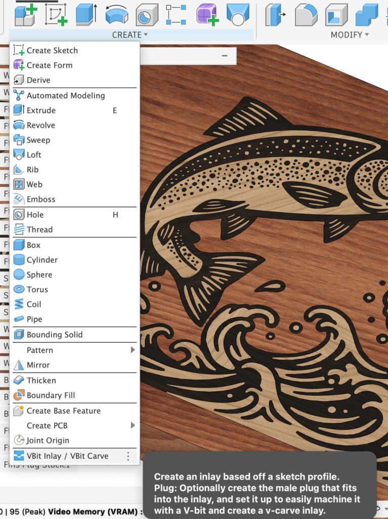
In the Design Workspace, in the Solid environment, click Create -> VBit Inlay / VBit Carve to bring up the primary command. YOU MUST BE IN HYBRID MODE! It will not work in “Part” mode or “Assembly” Mode.
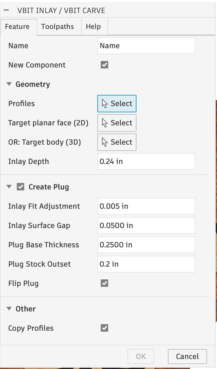
- Name: The name of your inlay; generated component names are based on this name.
- New Component: The plugin will always create new Components for: the Inlay, the Plug, and the Plug Stock. It will also create a new component for the target body if New Component is checked. If it is not checked, the target body will be directly modified. See Organization Recommendations for more details.
- Profiles: The closed profile shapes for the inlay. You can select entire Sketches, Profiles and Text objects. The sketch entities MUST be “on or above” your Target face or body, and should all be co-planar. The inlay is created by projecting “down” to the shape (ie: the perpendicular normal from the Sketch’s X/Y plane). To create a sketch “above” a 3D design, right click on the X/Y Plane and select Offset Plane. Offset the plane until it is above your main 3D body, and then create a sketch at this location. Note that the profile and Sketch do NOT have to be in the X/Y plane, and can be on any face or in any orientation. Note: Issues / Bugs / Limitations
- Target planar face (2D): Selecting a planar face will generate a 2D / flat inlay, and toolpaths better suited for 2D shapes by using 2D toolpaths (Engrave / 2D Pocket / Face). You can select more than one target planar face: select one first, and then multi-select all others and the algorithm will limit selection to faces that are planar. Multi-selecting all at once may select non-planar faces.
- Target body (3D): Selecting an entire body will generate a 3D inlay, and 3D toolpaths for complex shapes. Currently only one body can be selected at a time.
- Inlay Depth: How deep the inlay should be. I’d recommend 0.100″ for superficial inlays — although, that is the depth I use for my kitchen utensils, and they get regularly used and washed, and I haven’t ever had an issue with the inlay over the past several years. Use 0.230″ (6mm) for a deep inlay that needs more strength: something like a cutting board. The Inlay Depth is a constant; you do not need to change it to affect how well the plug fits into it. This value can later be customized after the inlay is created via the inlay_depth User Parameter. See Parameters for more information.
- Create Plug: Optionally create a Male Plug, and the associated Male Plug Stock that will fit into the inlay pocket.
- Inlay Fit Adjustment: This is the “glue gap” underneath the plug when in the inlay. You will need to set this to the value that works best for your particular bit and machine that you are using. See Finding the Inlay Fit Adjustment for more information. You can later change this by changing the inlay_fit_adjustment parameter.
- Inlay Surface Gap: The gap that will be above the inlay before the Plug Base Thickness. Keep it small to avoid having to do a deep inlay. I find 0.050″ works well. This value is a constant; once you pick a surface gap you don’t need to change it to adjust the fit, unless you find you need more or less clearance for some other reason. This value can later be customized after the inlay is created via the inlay_surface_gap User Parameter. See Parameters for more information.
- Plug Base Thickness: How thick the backing of the plug will be to hold it together. You probably want at least 0.25″.
- Plug Stock Offset: The plug stock will be created with an offset of this value. Have it be large enough of a value for you to clamp the plug down (ie: 0.200″ to 0.300″) from the top, or have it be 0 if you want to hold your plug down with some other manner (ie: tape/vacuum/etc). You can later change this by editing the generated sketch for the plug stock.
- Flip Plug: The plug is created right above the female pocket. If Flip Plug is checked, the plugin will flip the plug “upright”. It will also do a “Capture Position” at the top level of the file. If the plug is not flipped, the generated Setup for the plug will be upside down, and require some correction by the user to flip the z-axis orientation.
- Copy Profiles: When checked, the plugin will do a copy of the selected profiles to the target sketches. Otherwise, it will “Project” the inlay component into the other components to limit machining areas, but this will frequently give degenerate segment errors. Prefer to use “Copy Profiles” for designs that you import into fusion, but if you are drawing sketches inside of Fusion with bezier curves you may need to uncheck this feature.
Creating Toolpaths / CAM
The Toolpaths Tab:
- Create Pocket Setup & Create Plug Setup: If checked, the plugin will generate a Manufacturing Setup for the selected options, and pre-populate the correct toolpaths to machine it. The toolpaths will vary depending on if you targeted a Planar Face (2D) or a Solid Body (3D).
- Template: By default, the plugin will generate toolpaths based on the selected VBit and Clearance Bits. Instead, you can use a template of your own toolpaths, and the plugin will modify only the machining boundaries based on the target design. Using a template will disable all the other options. See Templates for more information.
- Swap X/Y Axis: By default the setup will have the X/Y/Z origin be the “bottom front left” of the workpiece. Checking this box will swap the x and y axis in the Setup, as I like to mount long pieces along my y-axis, and cutting boards are usually long in the x-axis. It does it by setting the X-axis to the y-axis in the setup.
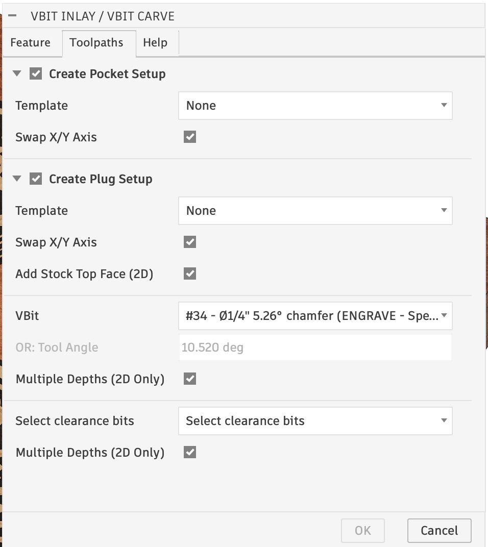
- Add Stock Top Face (2D): For plugs, it is good to face the stock top, and this will add a toolpath to do that, limited to the plug’s profile. It uses the largest clearance bit for the surface op.
- VBit Selection: The drop down list will show acceptable v-bits and flat bits that are currently in your document. You can add bits to your document by going to the Manufacturing workspace, click Tool Library, and drag tools into the current document. You can also select these later, but if you select them later you need to ensure you keep the “Tool Angle” in sync.
- Tool Angle: If you don’t select a bit, you must set the tool angle, which assigns the parameter inlay_bit_angle. This is used for all the math, and must be set correctly!
- Multiple Depths: If checked, the toolpath generation will check the “Multiple Depths” option in the toolpath, and set the depth to the bit diameter.
- Clearance Bits: You can select as many clearance bits as you want, and they will be used from largest to smallest, and finally the VBit will be used to clear any area that the prior bits couldn’t get to. Some “Generic” bits will show up by default, and you can later choose the actual bits you want to use. The diameter is important for 2D toolpaths when using multiple clearance bits, which will be discussed later. For 3D, it is all done via “Rest Machining”, based on the prior operations.
Unfortunately, Fusion doesn’t currently have an API to show the standard “tool selection” dialog you normally see when creating toolpaths.
If you did not pre-select tools, the toolpaths created by the plugin will show up with a red exclamation point and be invalid. If this is the case, you can double click on an operation and manually select the correct tool you want to use. Ensure the tool’s bit angle matches the inlay_bit_angle Parameter. Otherwise, some machining offsets will be incorrect and your inlay will not fit. You can always change the parameter to match the bit you select.
Design: What the Plugin Generates
The plugin creates up to four new components under the currently active component (see Organization Recommendations), with the base “Name” you gave it.
- Name Pocket – A copy of the target body with the inlay pocket cut into it to the inlay depth. Only created if you checked “New Component”.
- Name Inlay – The actual finished inlay. This is mainly for a visual representation of the inlay and internal computations, and isn’t used for machining.
- Name Plug – The plug that fits into the inlay.
- Name Plug Stock – The “Stock Body” for the Plug when machining. This is a specific height above the plug to allow it to go “deeper” into the inlay. The height above is controlled by the inlay_fit_adjustment parameter.
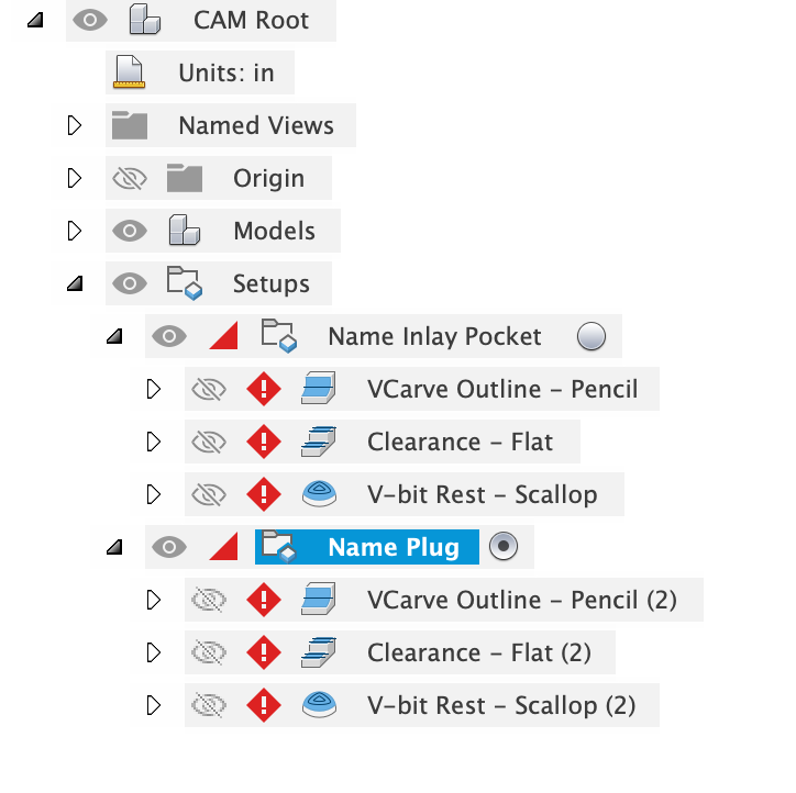
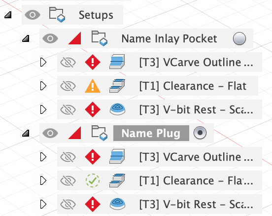
Manufacturing: The Plugin Generated Setups
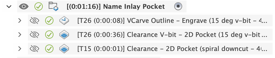
Two setups are (optionally) created in the Manufacturing Workspace, each with three basic toolpaths to do a VBit Carve. One for the inlay pocket, and one for the inlay plug.
1. Setup: Inlay Pocket
The Setup has the following customizations by default:
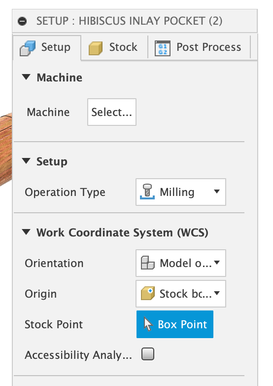
The WCS Origin is set to “Stock Box Point”, and the Stock Point is pre-selected to be the “Front Bottom Left” corner. This means the Z-zero is the bottom of the project, ie: the spoilboard. You can change this if you like.
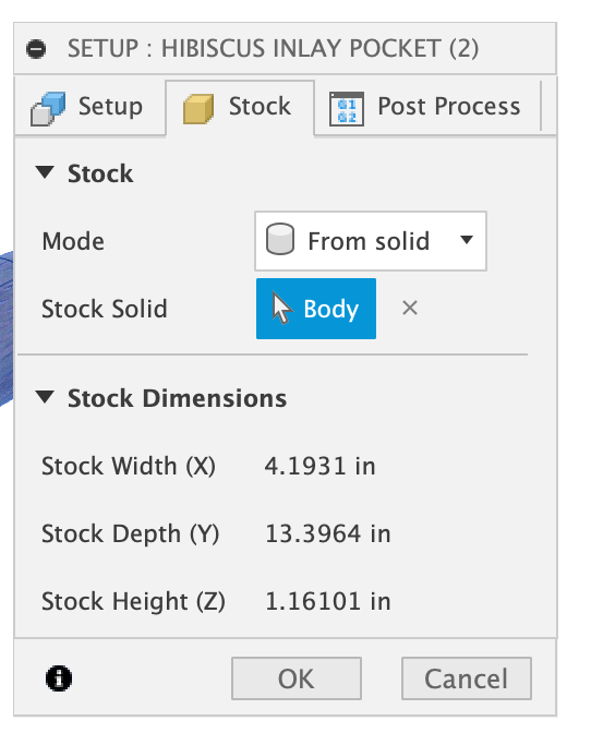
The Stock is set to “From solid” and the original Target Body is selected. For basic planar “2D” inlays, you can set it to “Relative Size Box” and change it to your liking.
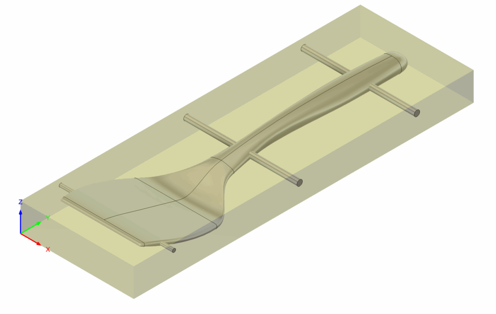
3D/Curved Inlays: This means when you are doing a 3D / Curved inlay, your “starting stock” should be the already carved 3D shape. You should have some other Setups that carve your shape before doing the Inlay Pocket. As an example, my Spatula project firsts machine the shape to the right in a prior Setup. After this setup complete you are ready to run the Inlay Pocket. You can simply take the toolpaths generated and move them to your previous Setup.
2D/Flat Inlays: I highly recommend adding a facing operation as your first toolpath! Face “to top of stock”. I generally start with stock *slightly* thicker than what my model says and face it off.
2D Toolpaths: Inlay Pocket
The pocket for a flat inlay will have three toolpaths generated.
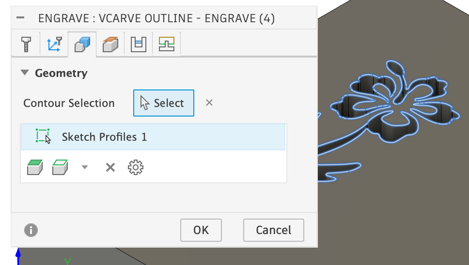
1st Toolpath: VBit Outline: A 2D Engrave toolpath. Engrave will only follow closed profiles.
On the Geometry tab, the Contour Selection is set to Sketch Profiles.
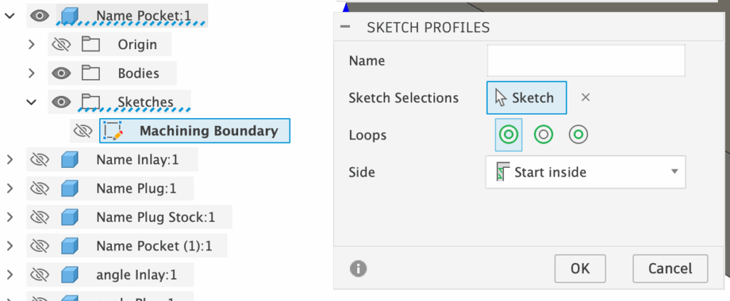
The Sketch Profile is set to a single Sketch: the Machining Boundary sketch that was created in the “Name Pocket” based on the selected design. It is also set with a Side of “Start Inside”, which is important!
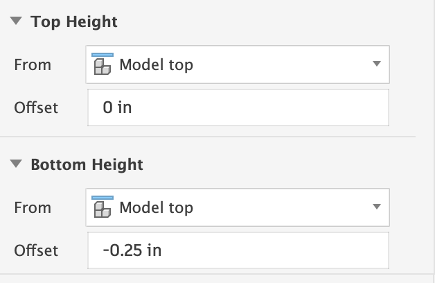
On the Heights tab, the Top Height determines where the design should be followed (Model top), and the Bottom Height is how deep it should go (the “flat height”). The Bottom Height is an expression. You can click the three dots to the right of the Value Input and select Edit Expression. You’ll see that the expression is set to “-inlay_depth” a Parameter which can be customized at anytime.
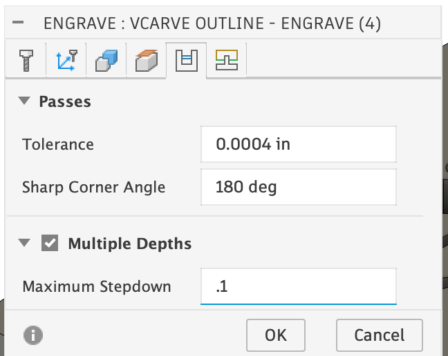
The Passes tab has a Multiple Depths option that can be turned on to easily limit the depth of cut with a Maximum Stepdown.
The Sharp Corner Angle is usually 165 degrees, but I set it to 180 degrees to make all corners sharp. You may get good results with it set to 165 degrees, and have a shorter machining time.
3rd Toolpath: Clearance 2D Pocket: A basic 2D pocket that that uses the selected flat end mill to do clearance. This is the last of the three toolpaths, but it makes more sense to discuss it second. The customizations to the op: Sketch Profiles are constrained just like the VBit Outline. The heights are also set similar.
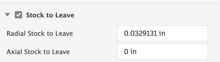
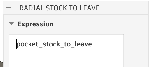
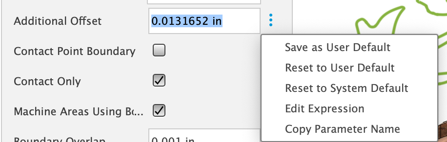
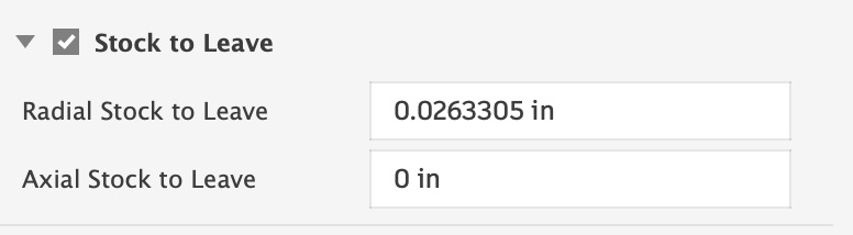
The most important part is the Stock to Leave on the Passes Tab. The “Radial Stock to Leave” is set to a specific value. This is an expression. You can click the three dots to the right of the Value Input and select Edit Expression.
The Expression is set to “pocket_stock_to_leave” which is a Parameter that the plugin adds. If you look at the Parameter, you will see its value is set to: tan(inlay_bit_angle / 2.0) * inlay_depth – this is some basic math that keeps the clearance operation away from the edges of the inlay by the exact amount that the v-bit leaves behind. This one of the main tricks for VBit Inlay Pockets.
2nd Toolpath: Clearance – V-bit: The second toolpath is ordered second to minimize tool changes, but it is the toolpath that will cleanup anything that the flat clearance bit could not get to. It is setup similar to the last toolpath discussed.
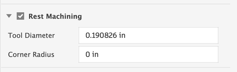
On the Geometry tab, the Rest Machining option is turned on. The Tool Diameter is set to another expression based on Parameters: pocket_clearance_tool_dia + pocket_stock_to_leave * 2.0 — this special value is what makes the 2d pocket v-bit get whatever area the “clearance tool” couldn’t get to.
Adding Additional Clearance Passes
You may want to do additional clearance bit passes with a larger diameter bit. Selecting multiple clearance bits will automatically chain the sizes together. The largest bit diameter will attempt to get most the material. For each next smaller diameter, it will have “Rest Machining” turned on, and the previous bit diameter is set to the next larger bit plus some extra math, such as: 0.25″+pocket_stock_to_leave * 2.0 – having the inches marker in there is important! You can modify the diameter if you need to.
Reordering 2D Toolpaths
By default, the v-bit operations are done first, and then the clearance bit is last. You can reorder these in any way you like; some people like to do the Clearance op first. Note that the clearance op assumes the previous one was ran, and may drag across an unmachined area if you reorder them!
3D Toolpaths: Inlay Pocket
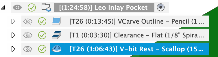
Three toolpaths are created, using the selected bits. Feeds and speeds are your own responsibility for your particular machine.
Lead in/Lead out: Currently all toolpaths have them set to zero/none. This is essential for the V-bits. For clearance ops, you might want to try a lead in, but it may cause issues with the toolpath computing correctly.
1. VBit Outline: A 3D Pencil operation – this is what does the main VBit Carving of the design. The Geometry has the Machining Boundary set to Selection, and is set to a Sketch Profile. The Sketch Profile is set to a Sketch named “Machining Boundary” found under the Inlay Pocket Component. This sketch is auto-created by projecting the inlay component. The Tool Containment is set to “Tool Center on Boundary”, and this is what allows the V-bit to come to a sharp point. Additional Offset must be 0, and Contact Point Boundary / Contact Only should both be checked (on).
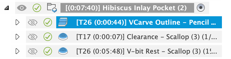

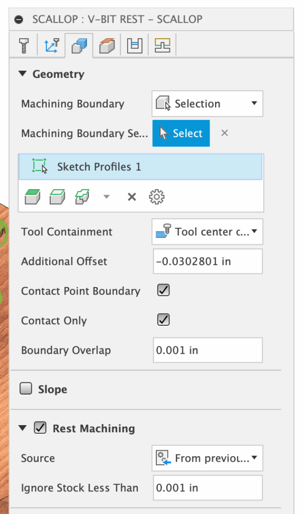
2. Clearance: For 3D shapes, the default is Scallop. For 2D/Planer, the default is Flat. Like the prior toolpath, the Machining Boundary is restricted in the same way, but the Tool Containment is Tool Inside Boundary and the Additional Offset is a specific value based on the prior bit angle used.
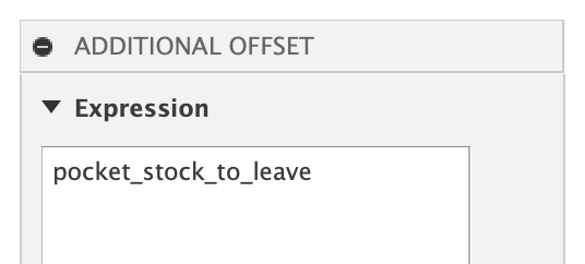
This is an expression. You can click the three dots to the right of the Value Input and select Edit Expression.
The Expression is set to “pocket_stock_to_leave” which is a Parameter that the plugin adds. If you look at the Parameter, you will see its value is set to: tan(inlay_bit_angle / 2.0) * inlay_depth – this is some basic math that keeps the clearance operation away from the edges of the inlay by the exact amount that the v-bit leaves behind. This one of the main tricks for VBit Inlay Pockets.
For Scallop, the Machine Areas Using Boundary is checked, and Boundary Overlap is set to a small value (0.001″), as that seemed to work best in my simulations and actual carvings.
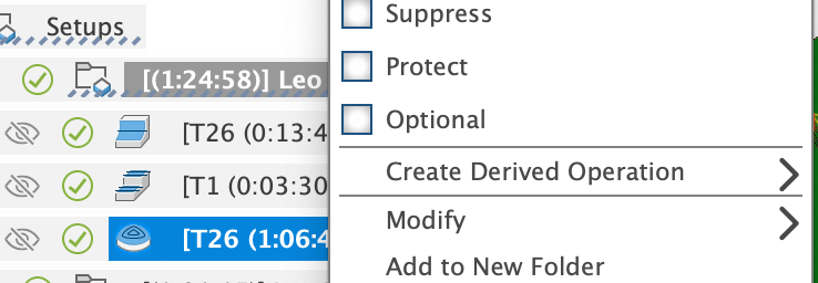
Alternatives: You can choose another Clearance operation by right clicking on the toolpath, Create Derived Operation -> 3D Milling -> and picking something else. Most the settings are transferred over, but ensure the Tool Containment is set to “inside”, as sometimes that gets reset. Morphed Spiral is a good alternative for 3D shapes.
Clearance Op notes: For 2D/Planer — sometimes the “Flat” toolpath fails to generate a result due to a Fusion bug. If that happens, try a derived operation of Scallop, as noted above. Scallop will sometimes miss parts; if it does, change the stepover to be smaller until it gets everything. You can use 2D Pocket for clearance.
Empty Clearance: Sometimes, the clearance toolpath will be empty because the bit is too large; try a smaller bit, or just use the v-bit (step 3).
3. V-bit Rest: The clearance bit will not likely get everything, and the v-bit needs to be used to finish off the rest. “Scallop” is the default op, for both 2D/Planar and 3D inlays. Since it is a V-bit, we want it to go right to the edge of the design, so the “Tool Containment” is set to “Tool Center on Boundary“, just like step #1’s Pencil operation. But the Pencil did the main carve, so we need to stay away from the edge by the same Additional Offset — an expression set to “pocket_stock_to_leave”. Note that it is negative and this is because “Tool Center on Boundary” needs a negative value to stay further on the inside. A positive value would extend it outside the center line.
Rest Machining is turned on, set to ignore stock less than 0.001″. This is what causes the v-bit to only get the areas that the Clearance operation missed. This means this operation has to be last for the rest machining to calculate correctly.
Reordering 3D Toolpaths
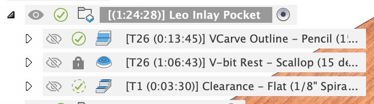
The default order would be: V-bit, Clearance Bit, V-bit. This causes an unnecessary tool change back to the V-bit at the end. However, moving the last “V-bit Rest” operation above the Clearance operation will cause it to re-calculate and not be correct (it’d try to remove everything the clearance should be doing). To solve this, you can right click on the V-bit Rest operation and check Protect. It will show “Protected” via a lock icon. You can then drag the protected toolpath above the Clearance operation. NOTE: if you do this, and you change something that makes the toolpaths need recalculation, you will have to move it back and unprotect it.
V-bit First or Clearance First
I prefer to do the v-bit portion first, and finish with the clearance bit. Some people prefer to do the Clearance operation first. If you want to do this, you can just drag the clearance operation before the VBit Outline. If you do that, you won’t have to Protect the V-bit Rest.
Machining with Multiple Depths / Stepdown: Most toolpaths have “Multiple Depths”, but Pencil does not. To work around this, right click on the Pencil toolpath and select “Duplicate”. Rename the first one “VBit Rough”. Double click on it to edit it. On the Passes tab, check Stock to Leave and set the Axial Stock to Leave to be half your inlay depth. IE: if your depth is 0.200″, set it to 0.100″.
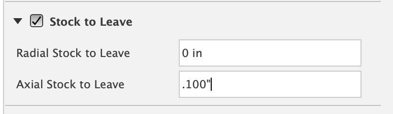
Doing this will generate a light first cut. The plug generally cuts deeper, and you may need to do two rouging passes with varying stock to leave.
************ Face Operation First *************
For flat/2d inlays, I highly recommend adding a facing operation as the very first thing you do that faces “to top of stock”. This ensures your model is the correct height, and the inlay depth will be exactly what you expect. Eventually I’ll add an option to add this toolpath in.
Setup: Name Inlay Plug
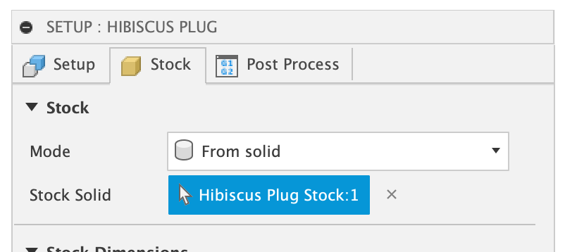
The Setup for the Inlay Plug is similar to the Inlay Pocket, but the Stock different. The Stock Solid is set to the “Plug Stock” that was created by the plugin.
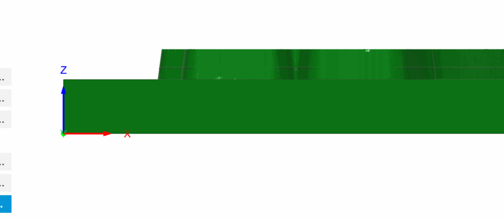
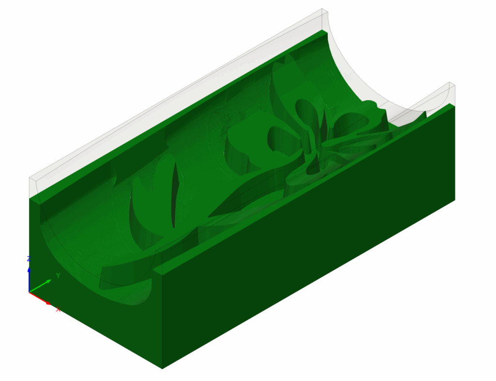
This is the main trick for a plug to seat deeper in the inlay. The stock is intentionally higher than the model; specifically, it is higher by the “inlay_depth minus inlay_fit_adjustment”. This can be seen in the images below from the side; the one on the left shows the stock (in translucent yellow) above the design (in gray). The image on the right is after the last toolpath runs, showing the v-carved edges and the inlay going “deeper” (higher) due to the extra stock.
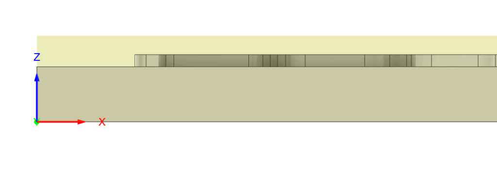
This amount could be the full “inlay_depth” if you set the “inlay_fit_adjustment” to be zero. That would be a perfect inlay, but that never happens in the real world, and in reality it will be gappy on the top because it prematurely bottoms out.
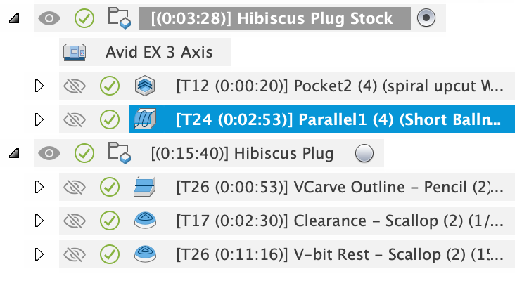
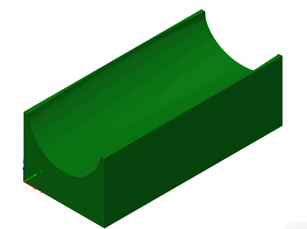
3D/Curved Inlays: Similar to the pocket, you should add another Setup to machine the “Plug Stock” as your starting point for machining the Plug. Consider the three images below: The first one shows the new Setup I created to machine the “Plug Stock”. The second image is the result of machining the “Plug Stock”. The final image is the result of running the “Hibiscus Plug” toolpaths to generate the plug. There is a way to combine all these into to one Setup, but I wanted to make it simple.
2D/Flat Inlays: Similar to the pocket, I highly recommend starting with a facing operation, and face to “Top of Stock“. Do not face to “Top of Model”, which is the default setting for a facing operation. If you do that, the plug may still fit (it is surprising), but it will definitely be gappy at the bottom of the plug when you cut it in half. This is essentially what would happen if you set inlay_fit_adjustment to the inlay_depth; if they are equal, there will be no extra part to fit into the plug (but despite that, wood moves, and it may go in when using sharp angled v-bits).
3D Toolpaths: Name Inlay Plug
The toolpaths are virtually identical to the Inlay Pocket Toolpaths. I will only cover the differences:
1. VBit Outline: The Machining Boundary Selection is set to the “Machining Boundary” Sketch found under the Plug component.
As noted in Multiple Depths, the VBit Outline for the plug in particular may need to cut really deep (inlay depth plus the surface gap), and setting up multiple depths by duplicating this toolpath may be necessary for your machine!
2. Clearance: The Machining Boundary Selection is set to the “Clearance Machining Boundary” Sketch found under the Plug component. This sketch has the bounds of the plug slightly offset by the radius of the cutter to allow it to stay entirely within the plug bounds (ie: not get the sides) and machine all areas. The amount it is inset is the: “plug_stock_to_leave”.
3. V-bit Rest: The Machining Boundary Selection is set to the “Machining Boundary” Sketch found under the Plug component and the amount inset is “-plug_stock_to_leave” being on center to the sketch.
These are the main differences from the Pocket Setup and toolpaths.
Parameters
Inlays can be customized after creation by modifying Parameters. Parameters are global and affect all inlays in the document. I would like to change this at some point to have different inlays with different parameters, but for now, this is how it works.
****** For known parameters that work with specific bits, see the VBit Inlay Parameter List
In the Design Workspace, Solid Tab, click Modify -> Change Parameters to bring up the dialog:
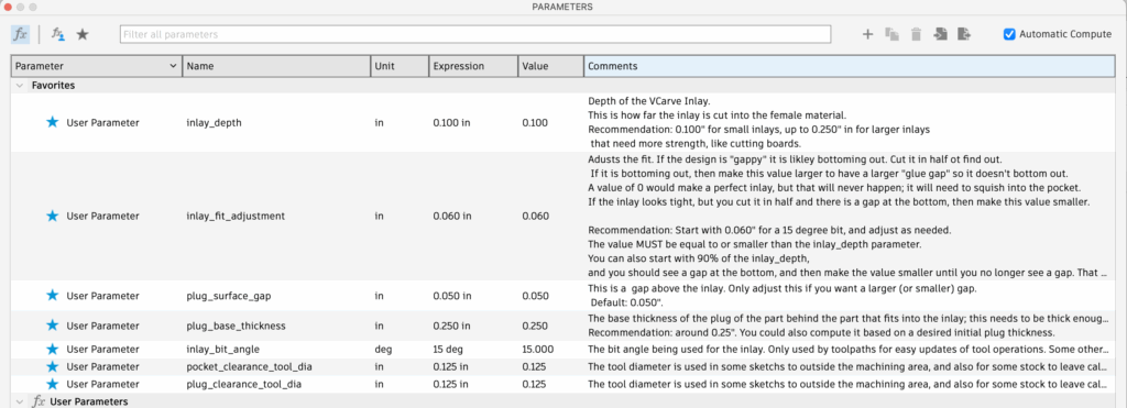
The parameters have a detailed comment that describes what they do. Be sure to keep the inlay_bit_angle in sync with the actual V-bit you are using, and ensure you put in the Inclusive Angle as discussed in the bits section.
The only parameter that you may have to adjust for your particular inlay fit is the inlay_fit_adjustment, which will be discussed next.
Finding the Perfect Inlay Fit / The Inlay Fit Adjustment
The fit of the inlay is controlled by the inlay_fit_adjustment Parameter. If you find a good value that works for a particular bit, inlay, and wood species, let me know! inlay_fit_adjustment can be from 0 to inlay_depth. A value of 0 is a “perfect” inlay, where your inlay plug would be exactly the depth of your inlay pocket. However, that usually gives a gap on the top, and wood will move and squish a bit when you glue and clamp. I use 0.060″ to 0.070″ for an end grain inlay that is 0.100″ deep with a 15 degree v-bit. It’s a surprisingly high value!
See VBit Inlay Parameter List for some known values to start with, and watch this video for how to find a good fit.
There are two main things that can go wrong when you fit an inlay:
1. Gaps on the top
If you create an inlay, and it has visible gaps on the top, adjust the inlay_fit_adjustment to be larger (probably by 0.010″ increments) and try again. The issue is the inlay is bottoming out, preventing it from closing the gaps on the top.
2. Inlay doesn’t go deep enough
If you create an inlay, and you have trouble fitting it in, or it does fit in with no visible gaps on top, cut it in half, and make sure it doesn’t have gaps underneath the inlay. If it does, adjust the inlay_fit_adjustment to be smaller until it no longer has a gap at the bottom or goes in as deep as you’d like (yeah, some people leave a glue gap). The issue is the inlay is not “steep” enough, and needs to have a deeper plug part.

3. Other issues
If you see gaps on the top of the inlay and underneath the inlay when you cut it in half, then you likely have an issue with your machine or the design itself:
- Design issues: The design may have parts that are chipping off during machining and the design has to be adjusted a bit to avoid this.
- Machine Squareness: Ensure you can cut a 5″x5″ square and that it actually measured 5″x5″ with calipers.
- Machine Tram: Ensure that your machine is trammed correctly.
- Feeds and Speeds: Incorrect feeds and speeds can cause jerkiness in CNC movement that will break off bits of the inlay. Dialing in your feeds and speeds is the only way to fix this.
- Machine Acceleration: Turning down your machine’s acceleration settings can greatly improve inlays.
- Clamping/press: Proper clamping with a press is generally required to get a really uniform inlay. I have only done small inlays, and use clamps. Eventually I’ll do some larger ones and discuss ways to make a press.
Organization Recommendations
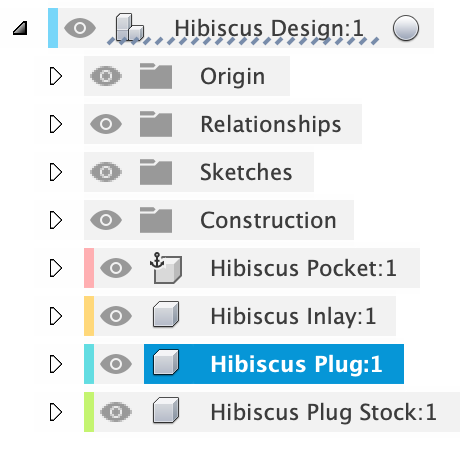
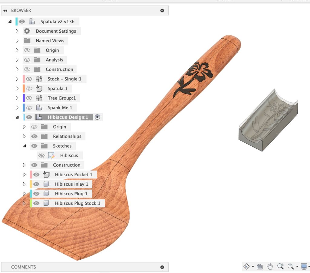
The current active component will become the parent for all the sub-components the plugin creates (Pocket, Inlay, Plug and Plug Stock). In general, before I run the plugin I will create a new empty component to contain all the relative sub-components, as they are all related. I also find this a good place to put my design sketch. This is good for a one-to-many relationship: you have one primary CAD shape, and you want to have a lot of different variations of inlays you can do on the main shape.
The example on the right illustrates this. I like to have a lot of different designs for my spatula inlay. I created a new empty component named “Hibiscus Design” and activated it. I created a Sketch in that component for my design. I then ran the plugin while the Hibiscus Design component as active, and it generated all the related components in one group. This makes it easy to hide or show the entire group.
When to NOT use “New Component”: In general, if you want to have a bunch of inlays targeting one particular body, I recommend unchecking “New Component”. This is generally only useful for flat 2D inlays. For 3D shaped inlays, you will likely need to machine your basic shape before actually machining the inlay pocket, so you need a copy of the basic shape without the inlay pocket to get it done correctly.
Using Templates
I’m still working on this part!
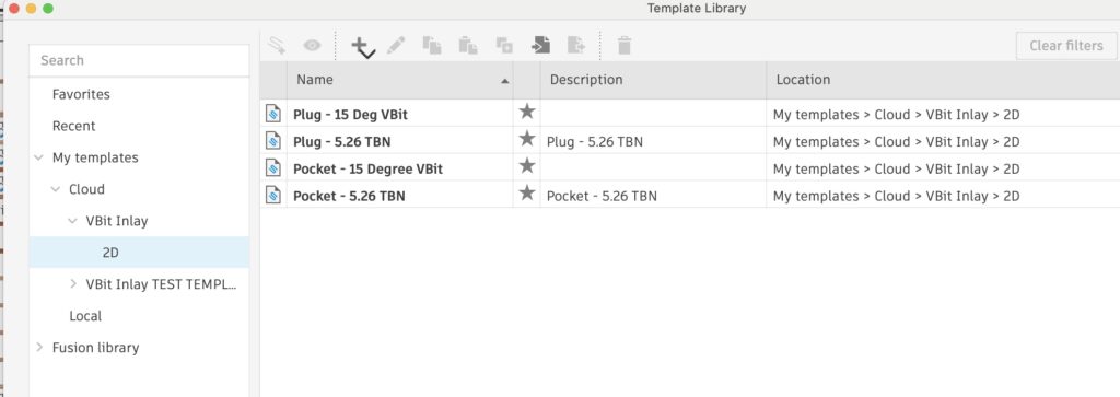
Right click on a group of toolpaths that work for you and save them as a template in “Cloud / VBit Inlay”, optionally organizing them by 2D or 3D, and maybe even by Plug or Pocket.
Once you do this, all the templates under “VBit Inlay” will show up in the plugin.
V-bit Tool Selection
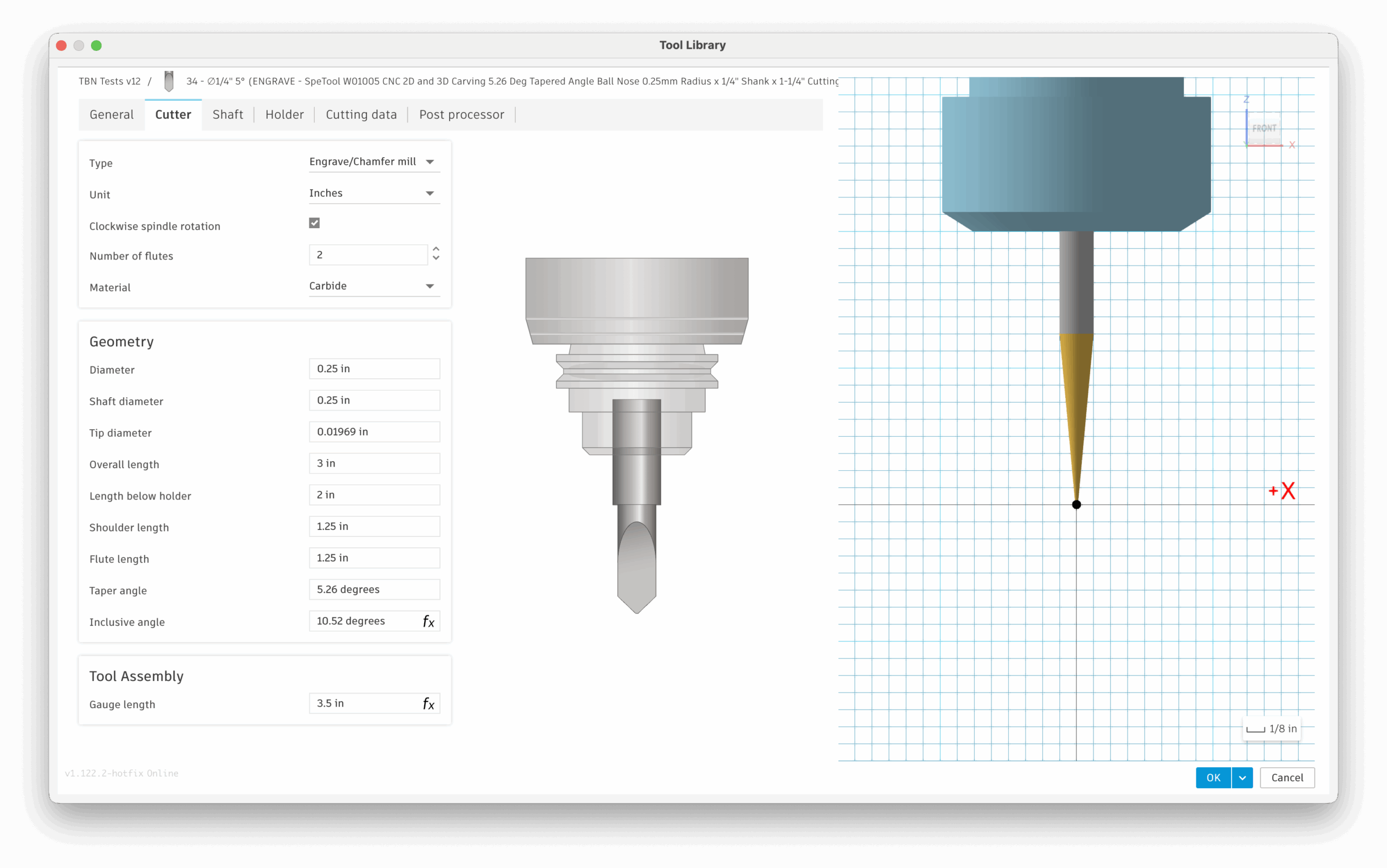
Bits that work with this technique are “Engrave/Chamfer mills” and “Tapered Mills“. “Tapered Mills” (ie: a tapered ball nose / TBN) will only work with the Pencil operation (3D Toolpaths) and will not work with the Engrave toolpath for 2D flat inlays. However, there is an easy work around to use a tapered ball nose (TBN) with Engrave, noted below.
I prefer fine detailed inlays, and use a 15 degree v-bit: Amana 15-degree v-bit. This bit has a 15 degree inclusive angle (the total angle), but I’ve also had good success with a Tapered Ball Nose.
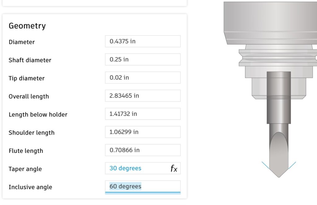
Bits are usually (but not always) named and sold by the Inclusive Angle, which is the total angle. The Taper Angle is half the inclusive angle, as shown to the right. Fusion will name bits based on the Taper Angle — so if you see it named as a 30 degree bit in Fusion, don’t get confused and put 30 degrees as the Parameter when it is really 60; things won’t work right!
However, some Tapered Ball Mills, such as Freud 72-400 5.4° x 1/16″ Tapered Ball Tip, are listed and sold by the taper angle! You will need to input the inclusive angle: 5.4°x2=10.8°. Just be aware of this, as it is important if you manually input the bit angle.
Tapered Ball Nose Mills (TBN bits): These will work fine with 3D toolpaths, but they will not work with the 2D “Engrave” Toolpath for flat inlays. You can copy your TBN tool and set the type to be an “Engrave/Chamfer mill” and set the tip diameter to be the ball diameter. Then it will work as for Engrave / 2D Toolpaths, but note that it will act like it has a flat bottom instead of a ball. For a steep TBN, this won’t cause much discrepancy with what it cuts.
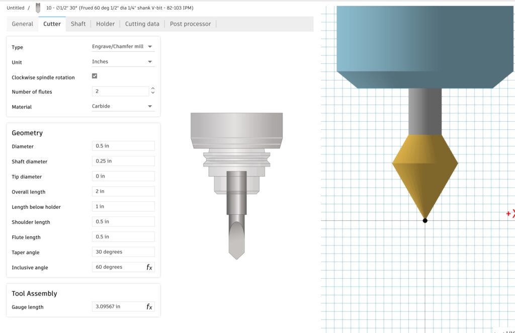
IMPORTANT: Pure V-bits, like shown below, will not work with the Pencil or 2D Pocket op (toolpath generation will fail on the V-bit pass) unless you set a Tip Diameter. You can use a really small Tip Diameter, like 0.001″, to get it to work, and it shouldn’t affect the inlay. If you are using metric, type in exactly 0.001″ and hit enter, and it will convert it to 0.0254mm. If you put too small a value, it will never finish computing (ie: 0.0001″ will take forever).
Some people have their v-bits as a Spot Drill – you will have to re-create the bit as a Engrave/Chamfer Mill.
3D Inlays / Extreme Angles / Machinability
Note some potential issues when you create a plug that approaches the vertical edge of a piece. The curved inlay (Hibiscus Flower) on this handle is very close to the edge of the handle, and the handle isn’t very thick.
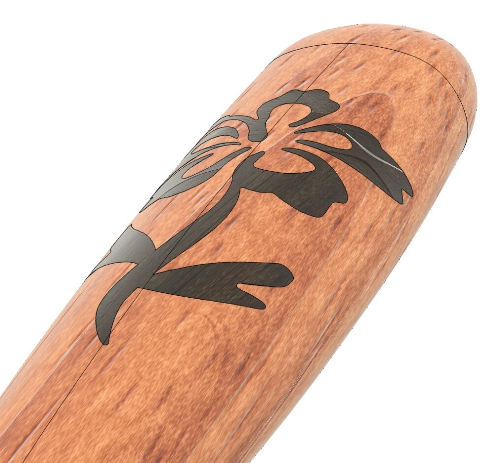
The resulting plug is shown to the right. It has two problems for machinability: the edges are past vertical and overhanging, which is impossible for a bit to machine. The curved edges are also too close to the edge of the inlay plug; another thing that a bit can’t get into.
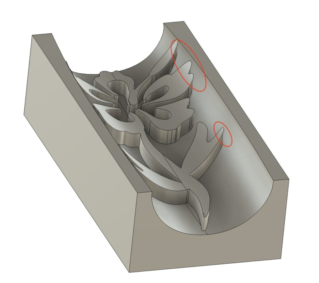
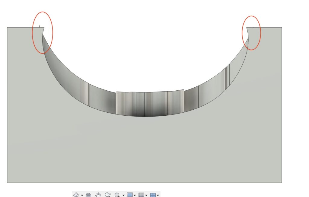
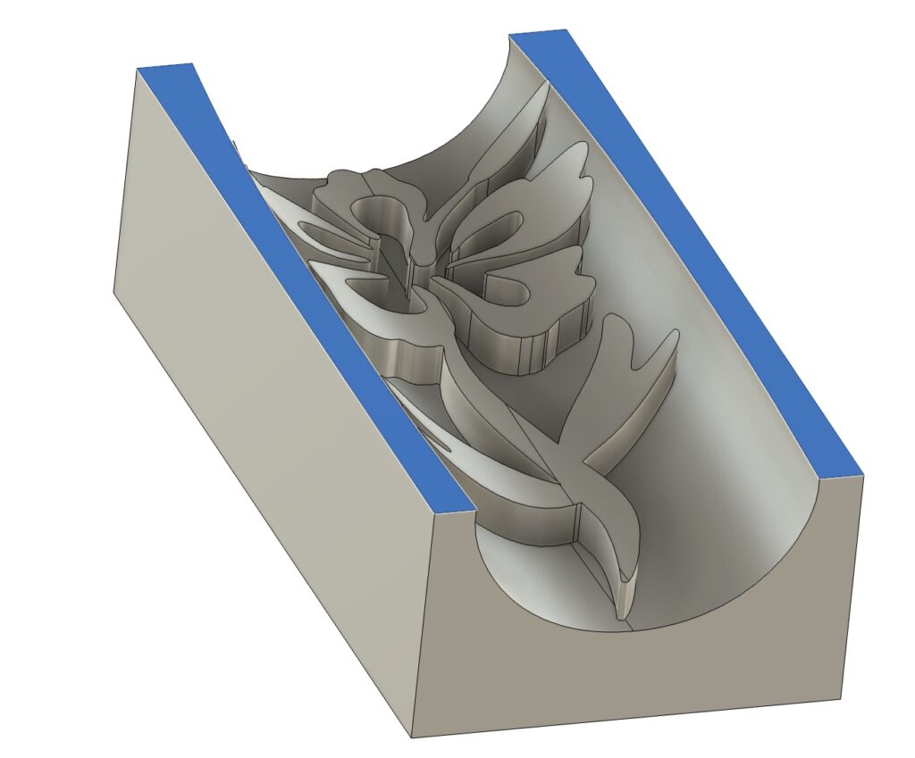
Machining this shape will result in a plug that won’t fully seat, and it will be gappy. (I know, because I accidentally did this!). The easy fix: select the top planar edges (shown in blue) and do a “Move”, and move them down until they no longer would cause a problem.
Issues / Bugs / Limitations
Empty CAM Browser
Sometimes the CAM workspace browser shows up empty, as shown to the right. Clicking the Show/Hide icon doesn’t help. You have to close the project and reopen it to get it to show up.
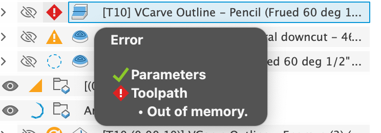
Toolpath: “Failed to Generate Pass” or “Out of Memory” or “Spins Forever“
If the Pencil and 2D Pocket operations will fail to generate a pass if you are using a pure v-bit with no tip diameter. Try setting a small tip diameter, as discussed in v-bit selection.
A “Tapered Ball Nose” bit will not work with the 2D Pocket operation unless it is setup as an Engrave bit, also as discussed in the in v-bit selection.

Clearance toolpath leaving extra stock (2D)
IE: The clearance toolpath is leaving a small ridge next to the v-carve toolpath and not cutting enough material. This is controlled by the radial “Stock to Leave” setup in the toolpath, and too much stock is set to leave; it is all controlled by parameters and math.
Possible cause: the inlay_bit_angle Parameter may not quite match the actual bit angle parameter.
Possible cause: Your bit’s setup tip diameter doesn’t match the actual bit tip diameter (note the hack work around of using a small tip diameter of 0.001″ for pure v-bits shouldn’t drastically affect this).
Possible cause: Machine tolerances being too large; make sure your machine has little backlash (tight belts).
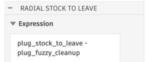
If the above things don’t fix it, you can start modifying the parameters that control the “stock to leave” for the pocket toolpath. Modify the “plug_stock_to_leave” or the “pocket_stock_to_leave” Parameters (depending on which one you are having an issue with), and make the value smaller to have it remove more material:

Sometimes, with some bits, I was seeing this frequently happen with the plug, so I did add another parameter to address it directly for the plug to remove a little more material, controlled by the “plug_fuzzy_cleanup” parameter; make the value larger to remove more material:
Toolpath “gouge errors”
First, try unchecking ‘Copy Profiles’. This attempts to use a projection of the inlay shape. Copy Profiles will copy the profiles as the machining limits, however, some designs aren’t suited for the toolpath, specifically: 1. Overlapping lines/profiles, 2. Intersecting lines/profiles, 3. Open profiles. Generally the only solution is to clean up your vector files to ensure you don’t have anything overlapping or open.
Selecting a Sketch will sometimes “miss” closed profiles.
First, make sure you are using version 1.8 or higher, which works better. Some sketch curves don’t return the right information from the Fusion API, and this appears to be a bug in Fusion:
https://forums.autodesk.com/t5/fusion-api-and-scripts-forum/intersectwithcurve-not-returning-the-right-count-it-s-missing/m-p/13975825#M22499
The work around is to manually select your profiles.
RuntimeError: 3 : Projection of the selected spline/curve would result in a degenerate segment and cause future modeling problems!
I think this is a Fusion bug; be sure to use version 1.6 or higher and check “Copy Profiles” to avoid this. If you still get it, please let me know!!
Complex Vector Fails/Hangs generating a 2D Inlay & Toolpaths
Unfortunately, sometimes Fusion hangs on complex designs. Trying a 3D target, even for a 2D face, will sometimes work around this issue.
The toolpath generation will sometimes fail to fully create, or the areas it machines will be incorrect. This seems to be due to the vectors in the Sketch. Sometimes you can trick Fusion into working with various tricks without using the Sketch:
- Removing the Sketch Limits for the Pencil toolpath for the first VBit Carve – this will machine all small areas
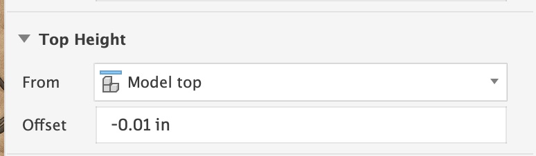
- Using a “3D Flat” toolpath for clearance, don’t use any sketch confinement; use the Silhouette as the boundary. Set the Stock To Leave to be “pocket_stock_to_leave”. Set the Top Height to be “Model Top” minus a small amount of(ie: 0.01″) to avoid machining the flat top.
- Do the same for the “V-bit Rest”
2 : InternalValidationError : face
This seems to be a bug in Fusion 360 caused by SketchText objects. In your Sketch, Right Click on the text and “Explode Text”. Then try again with the exploded text.
Jerkiness in CNC Machine Movement
Possibly too dense of a Gcode file. Increasing the Smoothing value may help to reduce the size of your GCode file.
Updating Text After Generation
You can select text profiles in a Sketch, but editing it after the inlay was generated will likely not work. There is no way for me to keep track of the bodies changing. You could manually fix it up, but it is probably easier to just run the plugin again when you change the text.
Feature request: Allow multiple “Target Body” for 3D Inlays
It would be nice to allow multiple bodies to be selected; currently you can only select one.
Feature request: Allow different parameters per-inlay
Moving to a single “custom feature” in the timeline would allow this. The API is in beta for Fusion, and it will take a lot of work to re-write it to support it.
Bug: Parameters not working in any of the toolpaths
Two users have reported that the parameters are not working in the CAM/Manufacturing portion of Fusion. This seems to be a bug in Fusion, and has been reported via the Forums and directly to the the developers via email (https://forums.autodesk.com/t5/fusion-api-and-scripts-forum/parameters-not-showing-up-in-cam-manufacturing-workspace-for/m-p/14131644#M22795). I’m sure it is something I’m doing in the plug-in with how Setups are created, but I can’t narrow down what causes it, as I can’t make it happen. Autodesk can see the problem after it occurs (as can I), but neither of us can reproduce it on our systems.