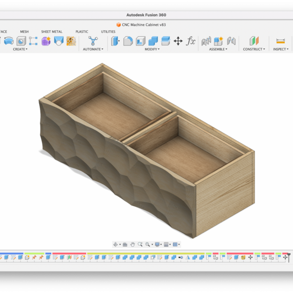
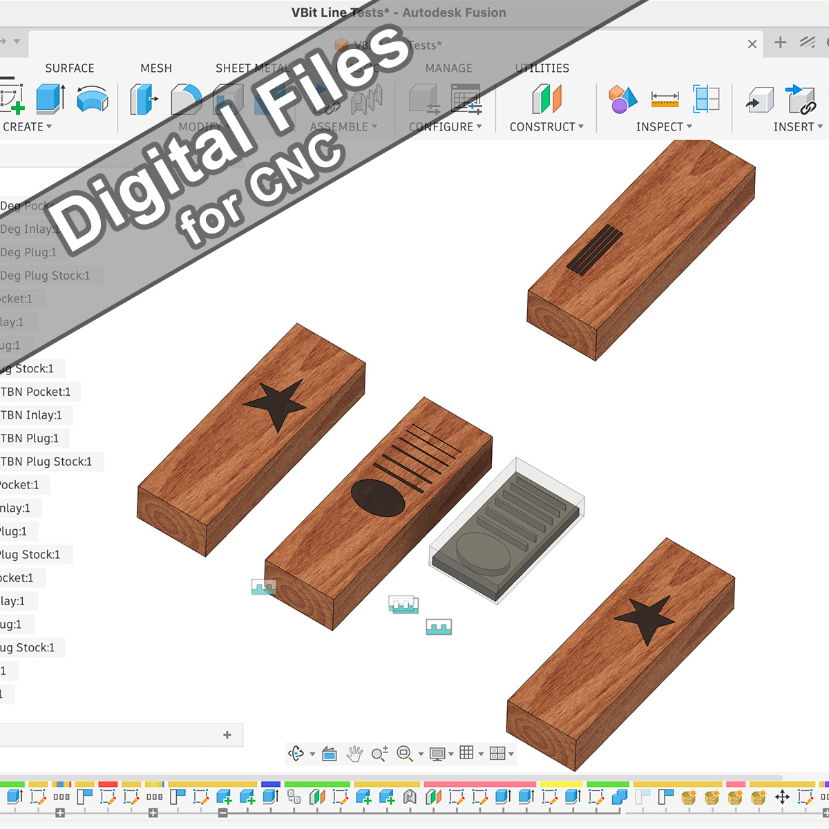
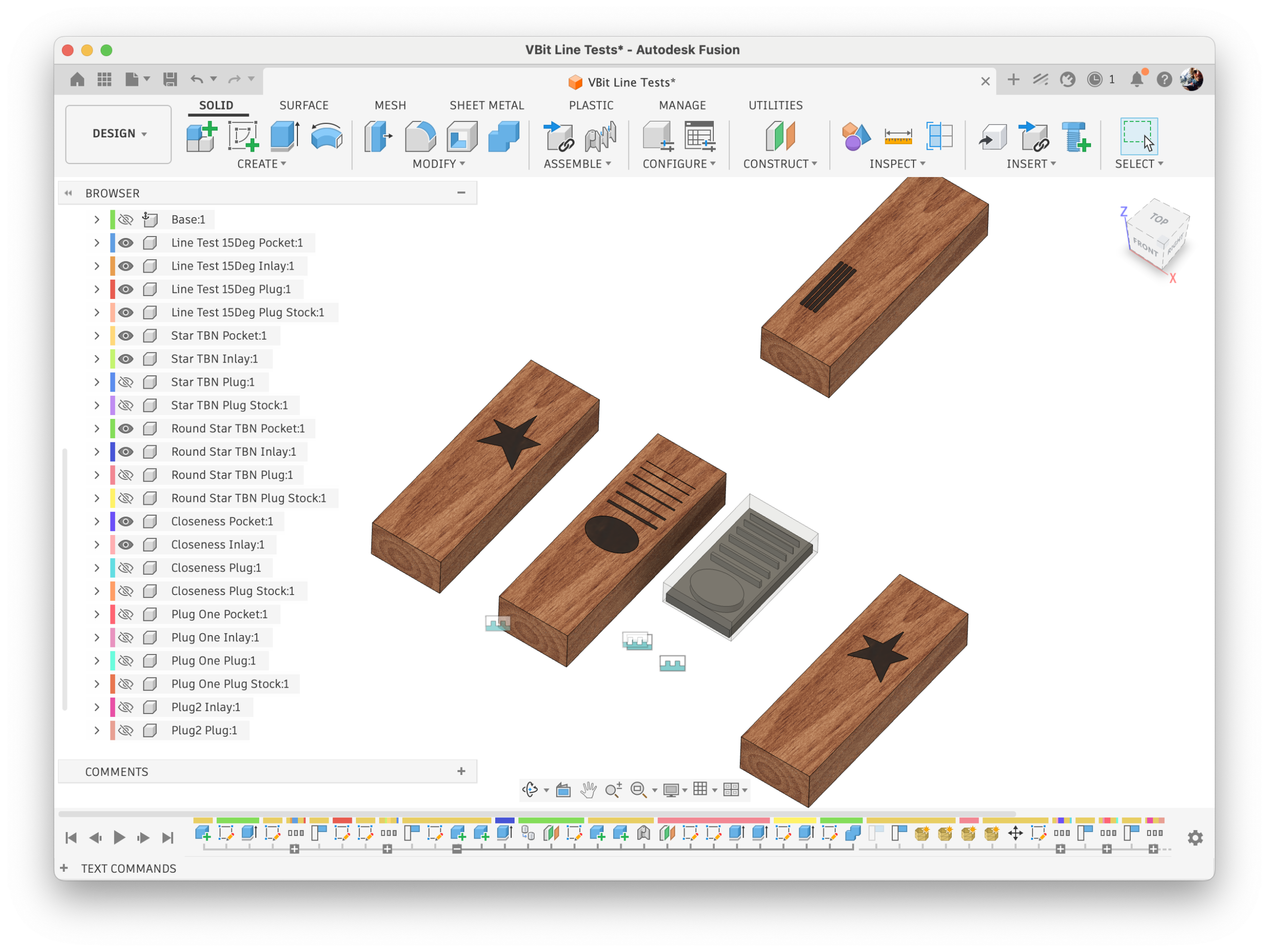
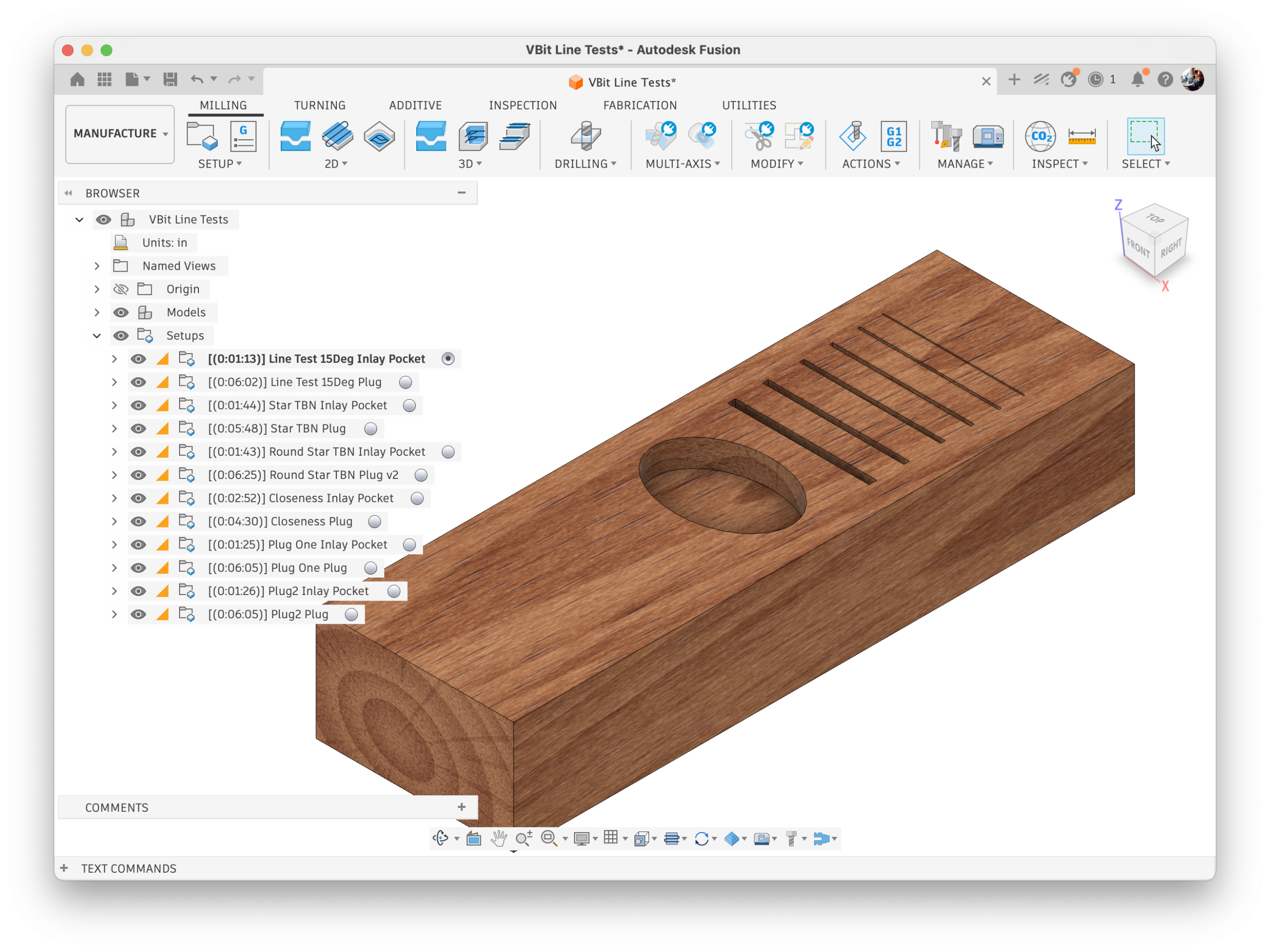
This is the Autodesk Fusion CAD/CAM file for testing how thin of a line you can do with a wood vcarve inlay, discussed in the video: VCarve Inlay Design Concepts
Also included are my CAD drawings for the two bits I discuss, with links to the bits I used below.
The CAM / toolpaths are setup for the line test and star drawing. The line test is setup for a 15 degree Vbit and a the star test was done with a tapered ball nose. You must change the inlay_fit_adjustment and inlay_bit_angle based on the bit you are using and the test you are doing, BEFORE exporting CAM toolpaths to Gcode. Please read the VBit Inlay Documentation for more information. Parameters I used, and design limitations:
- 15 Degree V-Bit: https://amzn.to/4oeJ1Zo
- inlay_depth: 0.240″
- inlay_fit_adjustment: 0.070 to 0.080″
- inlay_bit_angle: 15 degrees
- Min line width: ~0.035″ to ~0.040″
- Full depth 0.240″ line width: 0.068″
- Line width at 0.100″ depth: 0.031″
- Min corner diameter: 0.005″ absolute minimum, but 0.010″ is better
- 5.26 Degree Tapered Ball Nose / TBN: https://amzn.to/4aNb1zP
- inlay_depth: 0.240″
- inlay_fit_adjustment: 0.000″ to 0.0010″ (try: 0.005″)
- inlay_bit_angle: 10.52 degrees
- Min line width: ~0.048″ to ~0.050″
- Full depth 0.240″ line width: 0.064″
- Line width at 0.100″ depth: 0.038″
- Min corner diameter: 0.020″ absolute minimum, but 0.038″ to 0.040″ is better and what I generally use.
- Thin parts may need trimming
- 1/8” spiral upcut bit: https://amzn.to/4aGpo8o
- 1/8″ downcut bit: https://amzn.to/43nqiTe
- 3D Print Low Profile Toe Clamps